SpoolEse Scale Build Guide
This guide provides step-by-step instructions for building SpoolEase Scale - the filament weight module of the SpoolEase system.
Preparing the ESP32-S3
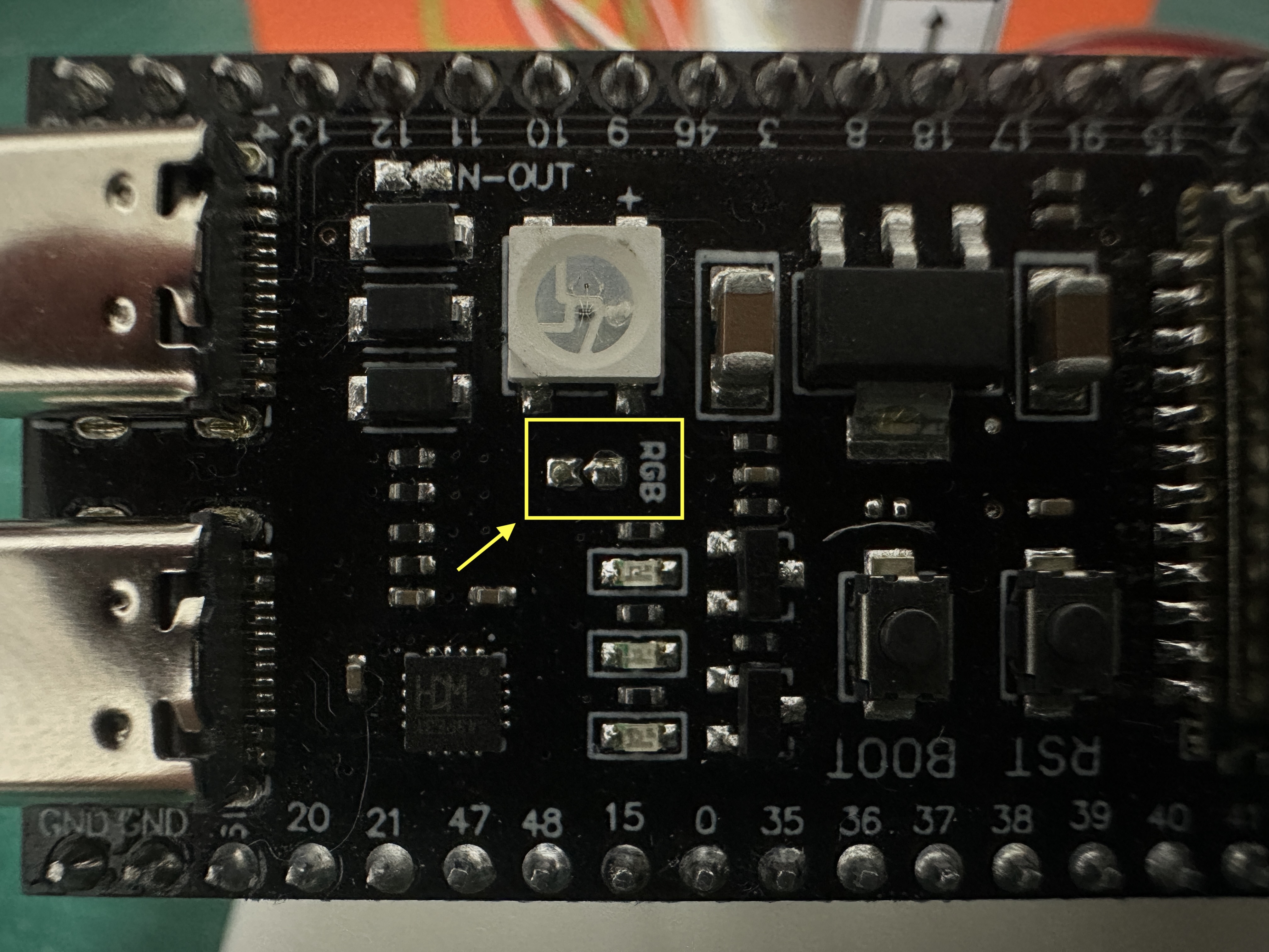
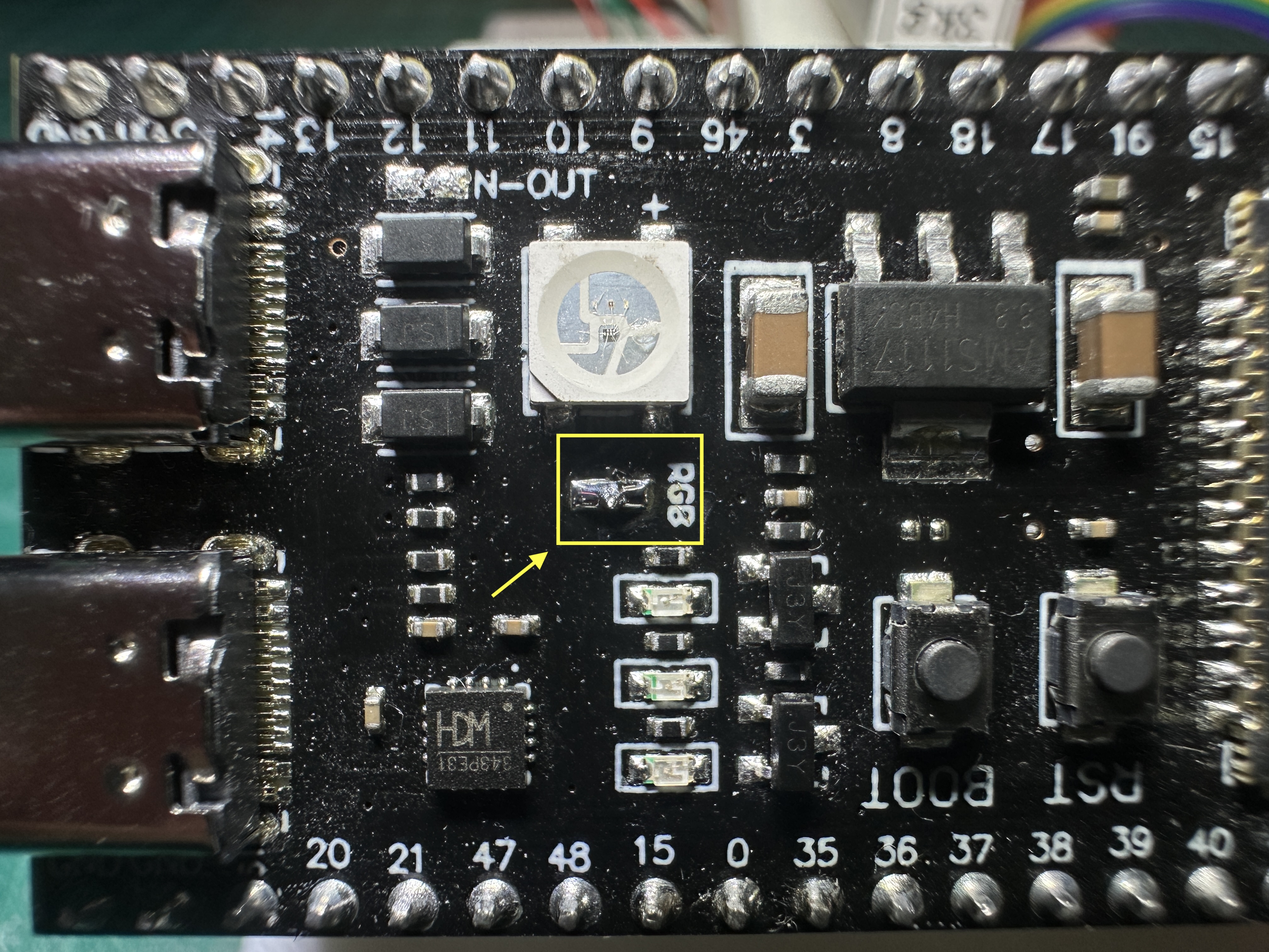
- To enable the front RGB LED functionality, solder a small jumper (two adjacent pads) on the board.
- This jumper is located directly adjacent to the large RGB LED, marked with 'RGB' label nearby.
- Only a minimal amount of solder is required for this connection.
- Verify successful bridging by using a multimeter to check continuity between pin 48 and any of the four led pins (only one would show continuity).
- While not mandatory, this step is highly recommended as it provides valuable status feedback from the SpoolEase Scale, particularly when not connected to the SpoolEase Console.
- Check the images below - first one Before bridging and the other After bridging
Assembly Instructions
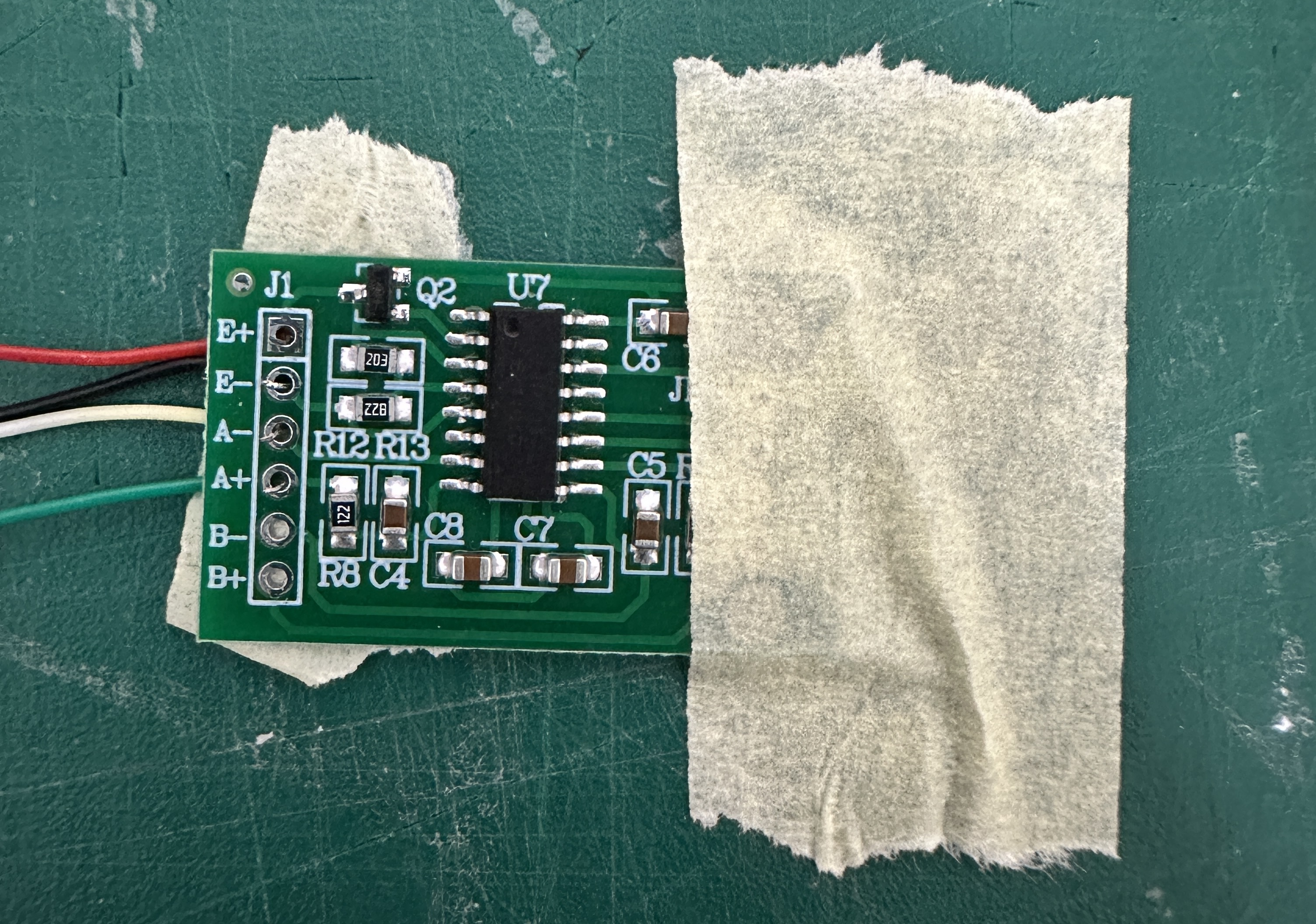
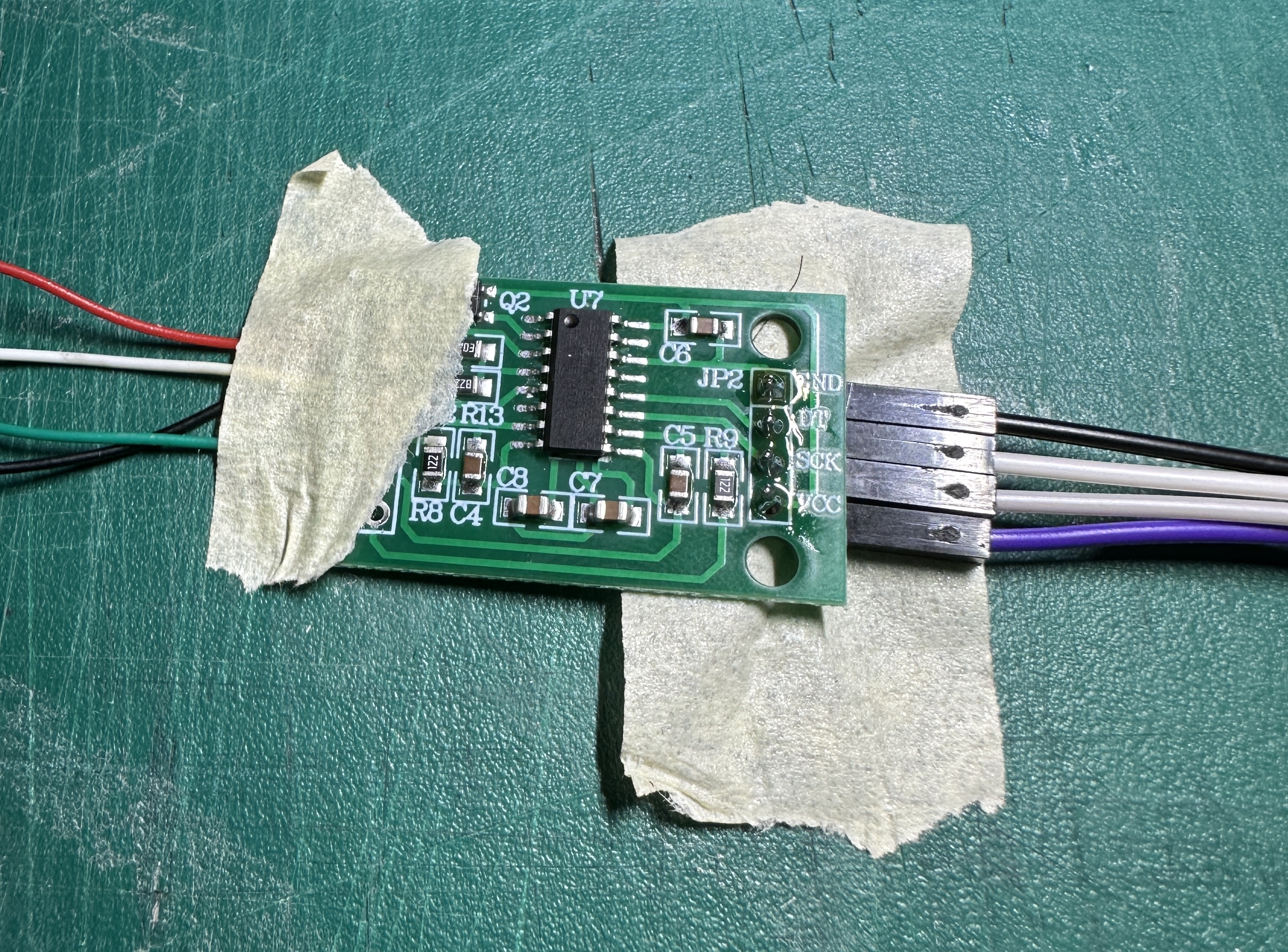
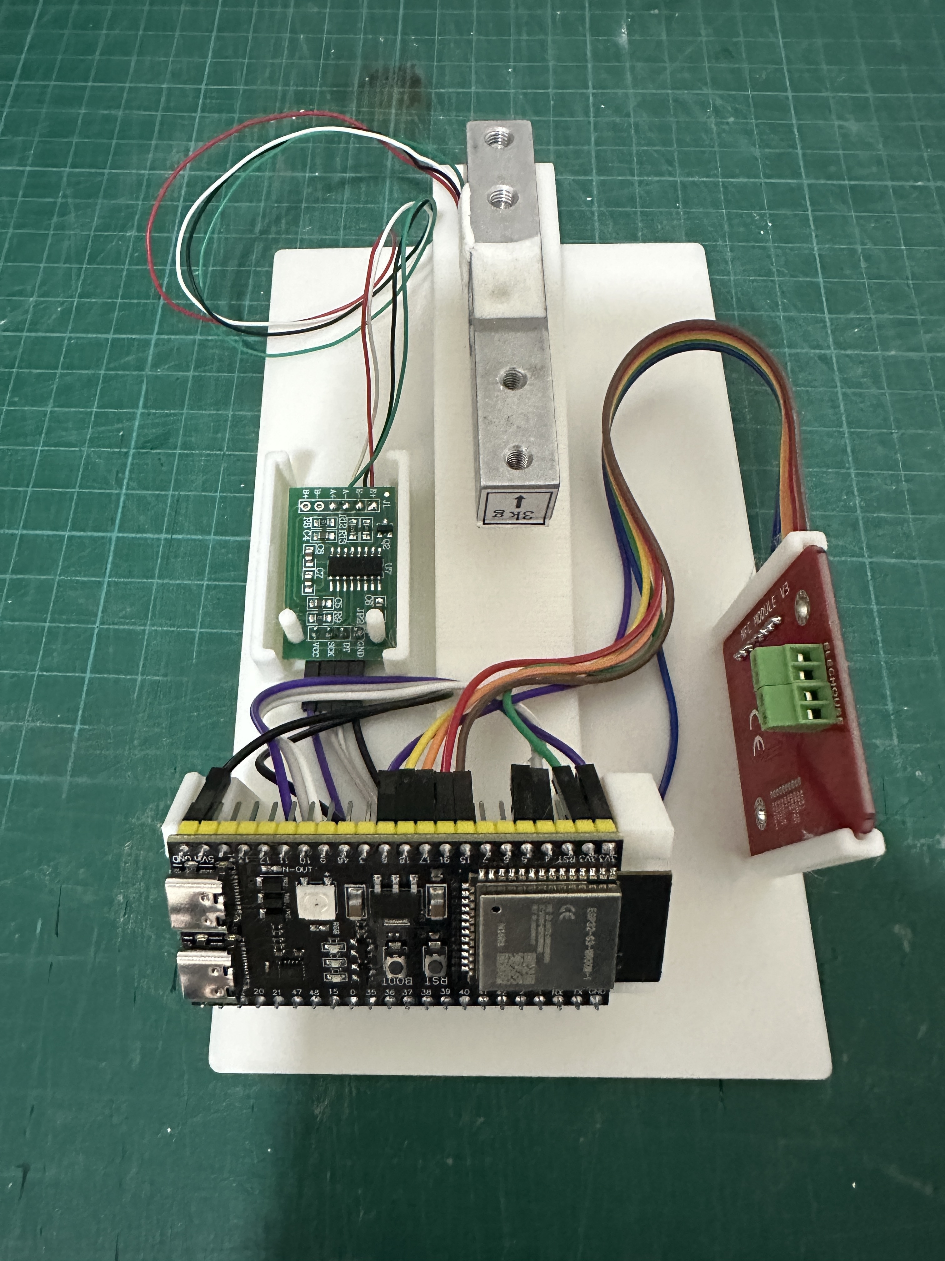
1. HX711 Wiring
The HX711 PCB has connection points on both sides:
- One side has 4 holes for ESP32-S3 connections
- The other side has 6 holes (only 4 used) for load cell connections
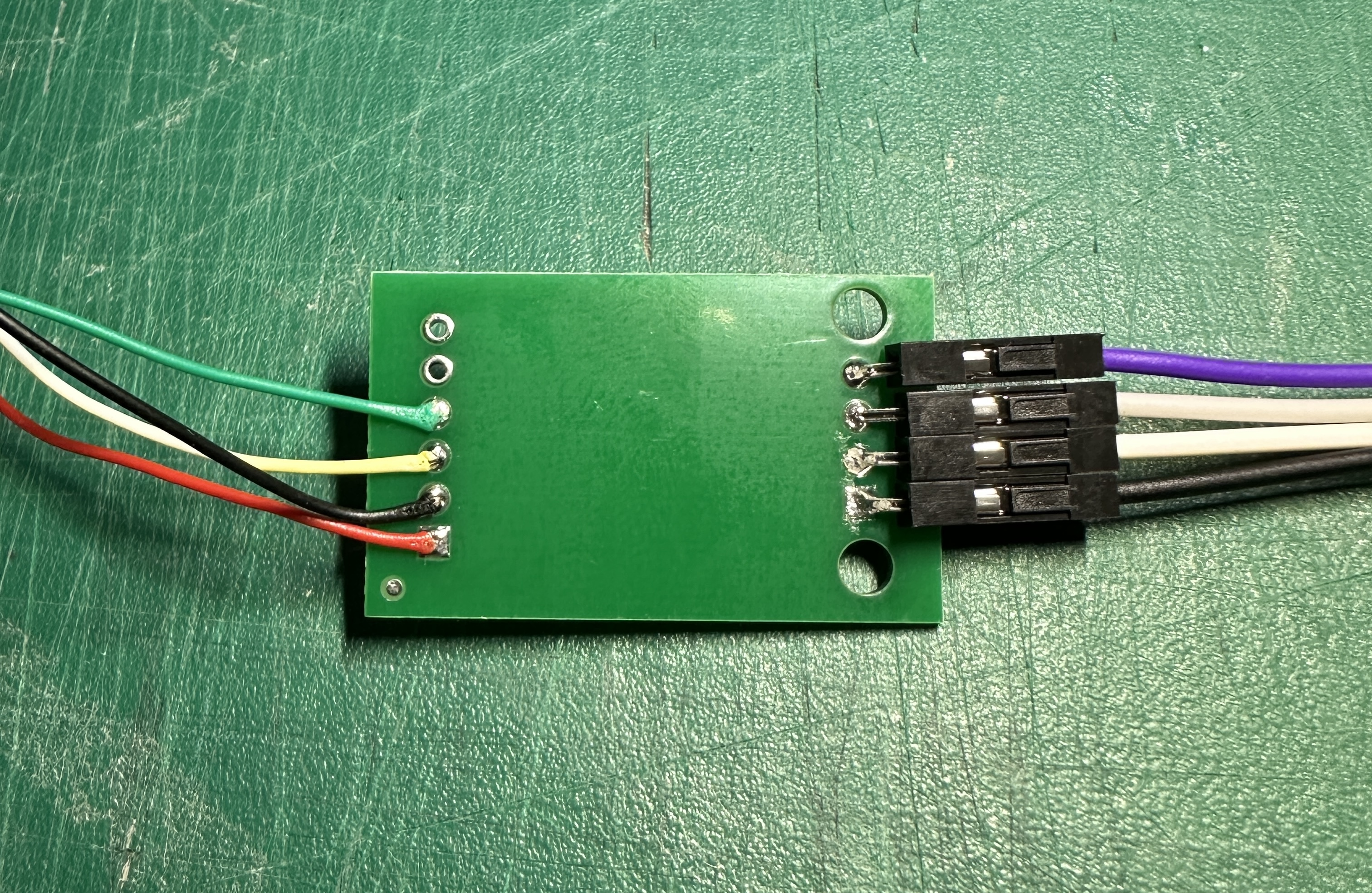
Begin by soldering the ESP32-S3 side connections (all 4 holes need to be wired). For the load cell side, precise wiring is critical. A helpful technique: insert wires through the holes, secure with masking tape, then solder from the opposite side.
Load Cell to HX711 Connection:
| Load Cell Wire Color | HX711 Pin |
|---|---|
| 🟥 Red | E+ |
| ⬛ Black | E- |
| ⚪ White | A- |
| 🟩 Green | A+ |
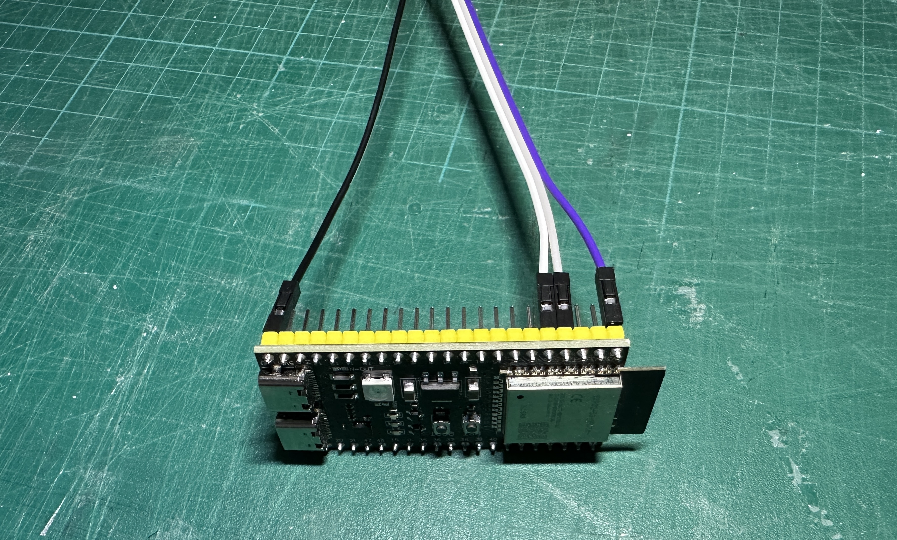
2. Connect HX711 to ESP32-S3
Connect the HX711 to the ESP32-S3 using the following pin mapping:
| HX711 Pin | ESP32-S3 Pin |
|---|---|
| GND | GND |
| DT | 5 |
| SCK | 4 |
| VCC | 3V3 |
Note: The ESP32-S3 GND is on one side of the board, while the other pins are on the opposite corner.
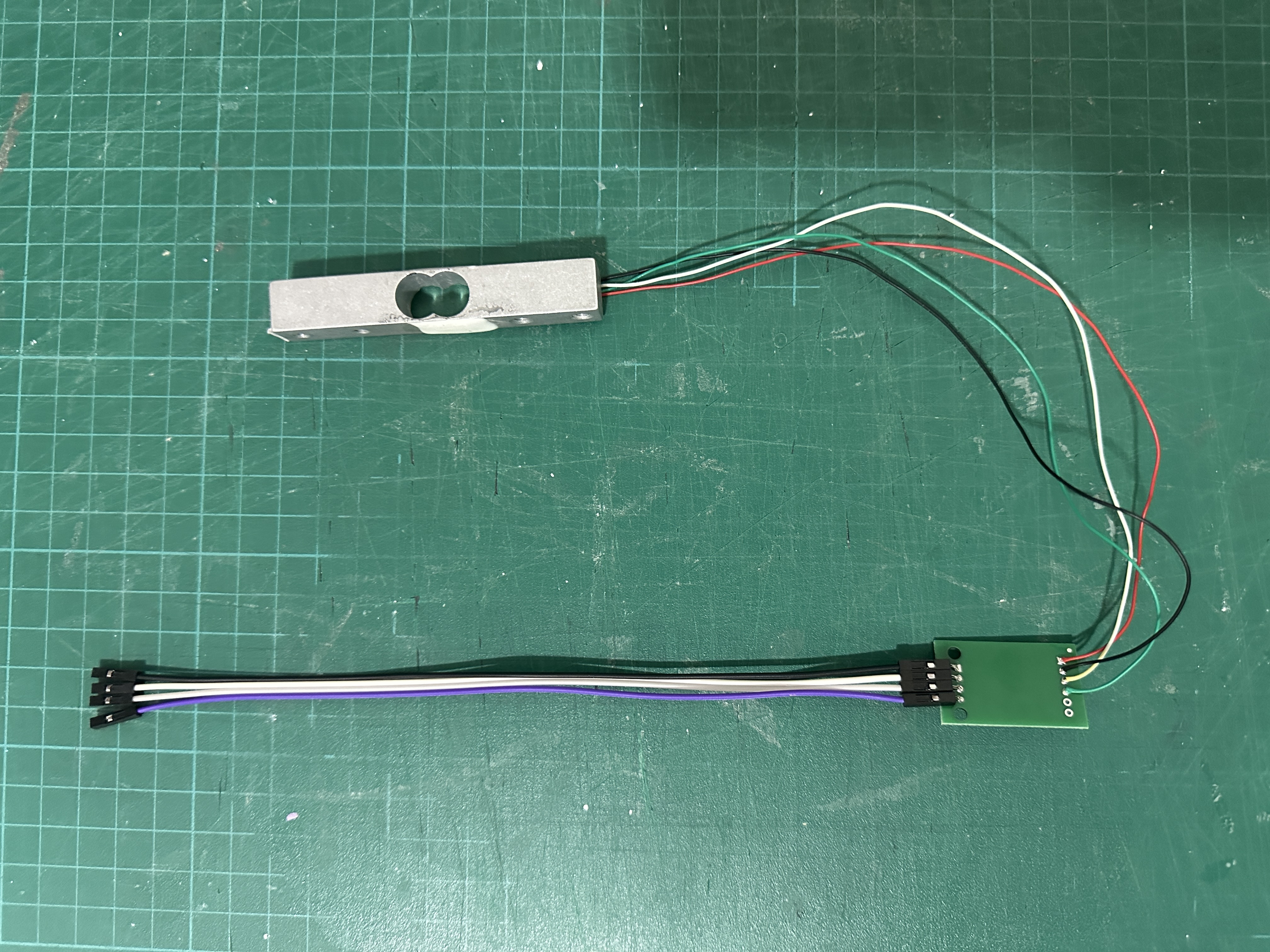
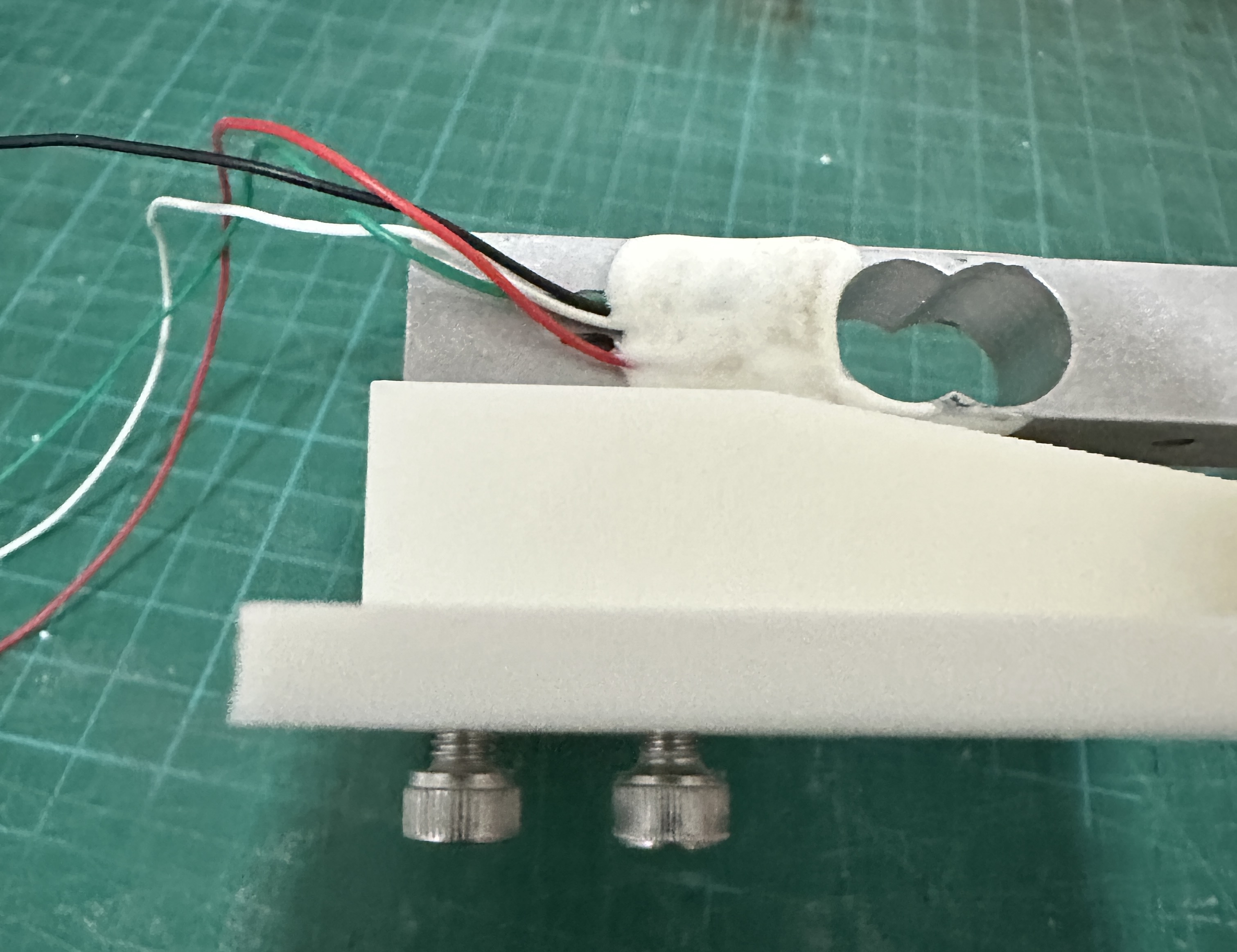
3. Mount the LoadCell
- Attach the load cell to the base using the two M5x30 screws
- Position the load cell so that the wires come out to the left
- Insert screws from the bottom of the base
- Tighten firmly to prevent any vertical movement of the load cell
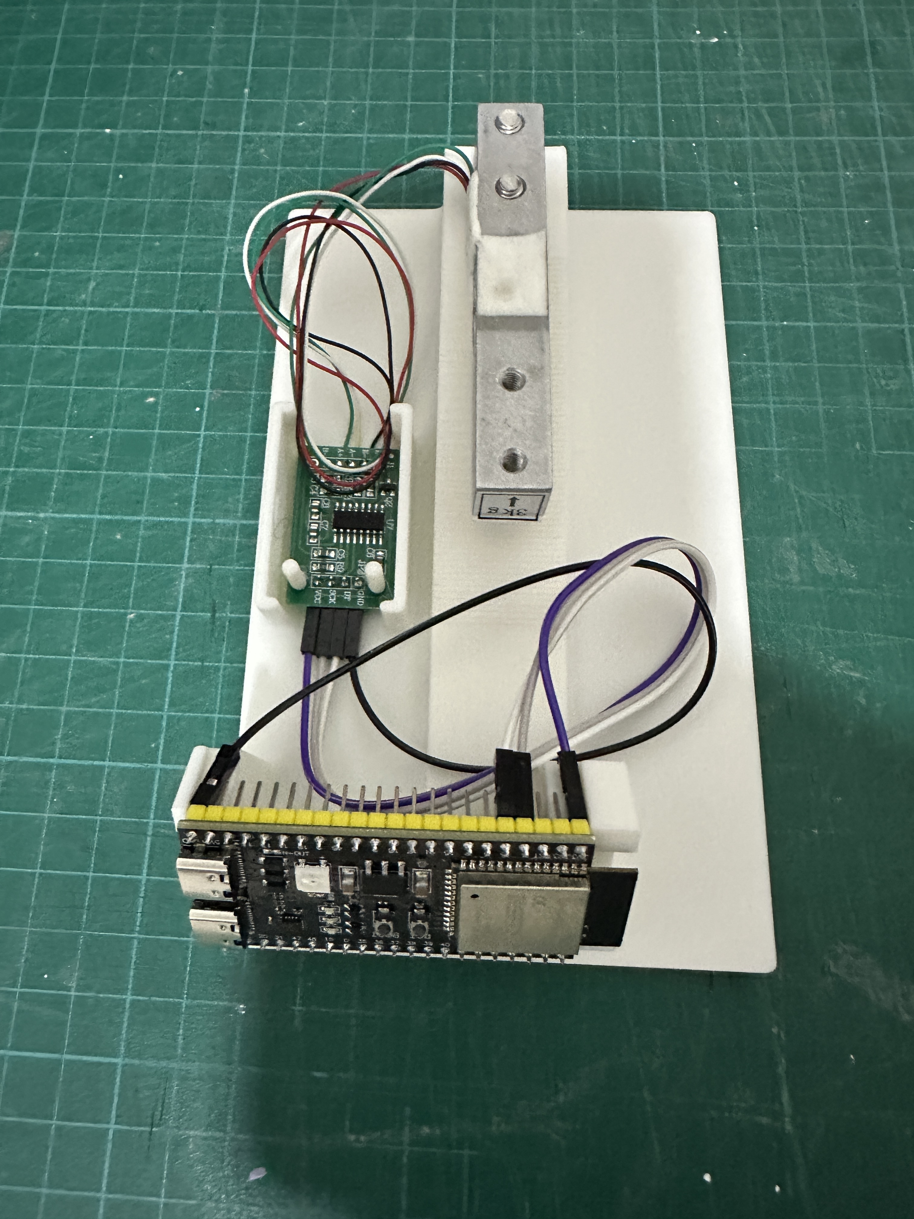
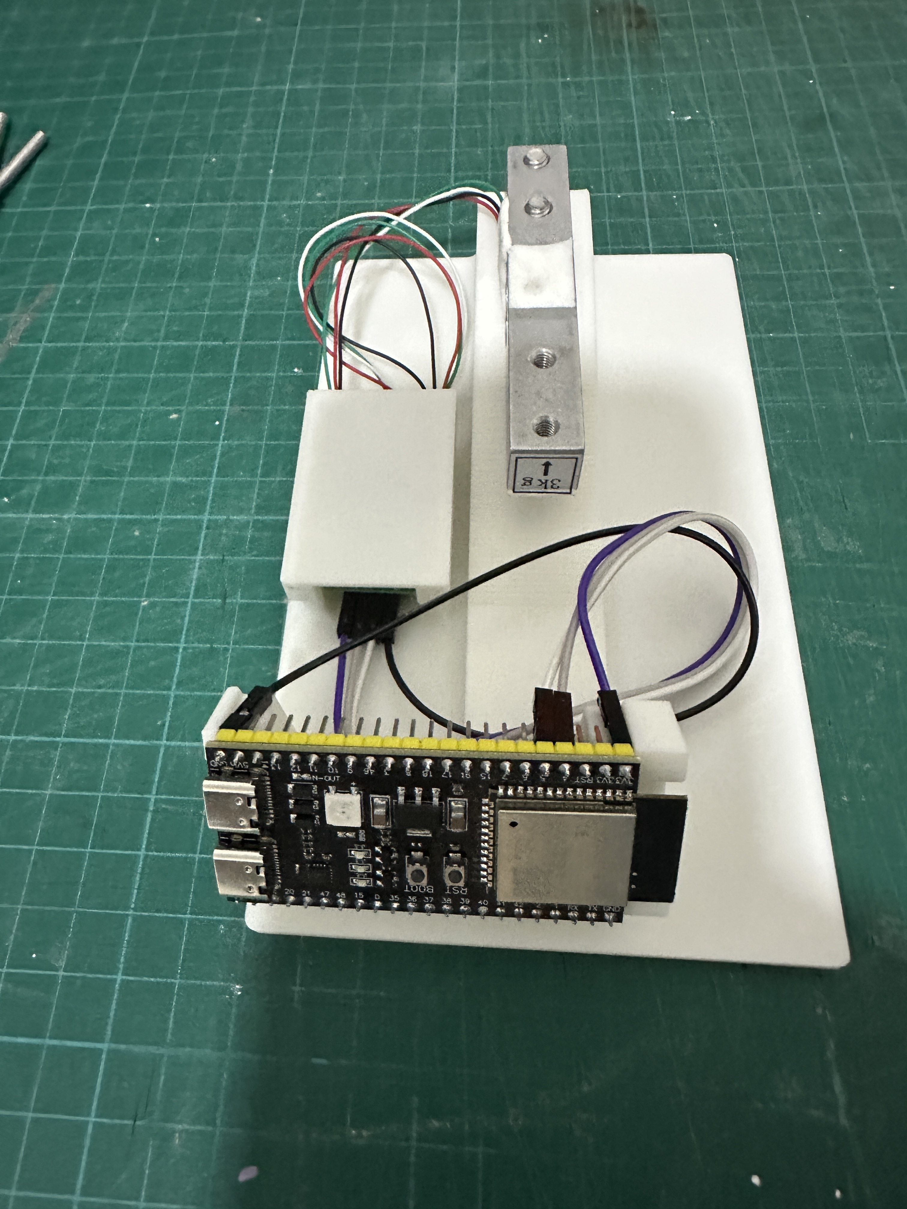
4. Install HX711 and ESP32-S3 on the Base
-
HX711 Placement:
- Locate the small compartment on the left side of the base with two 3mm poles
- Slide the HX711 (which has two 3mm holes) onto these poles
- Optionally install the appropriate HX711 lid (model includes two options) depending on your connector type
-
ESP32-S3 Placement:
- Position the ESP32-S3 in its designated location at the front
- Ensure it sits fully in place with all connections secure, it should have only very little room to move sideways if any
- The ESP32-S3 antenna should be positioned on the right side
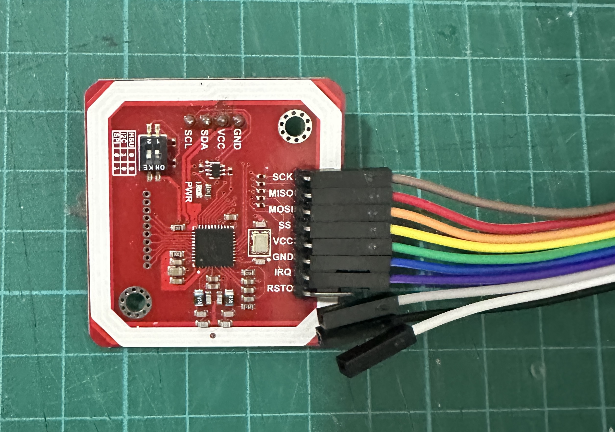
5. Optional PN532 Installation
As mentioned earlier, this step is optional and only needed if you want to add a tag reader to SpoolEase Scale. However, if you skip it, make sure to disable the NFC module in the SpoolScale Web Config to avoid errors.
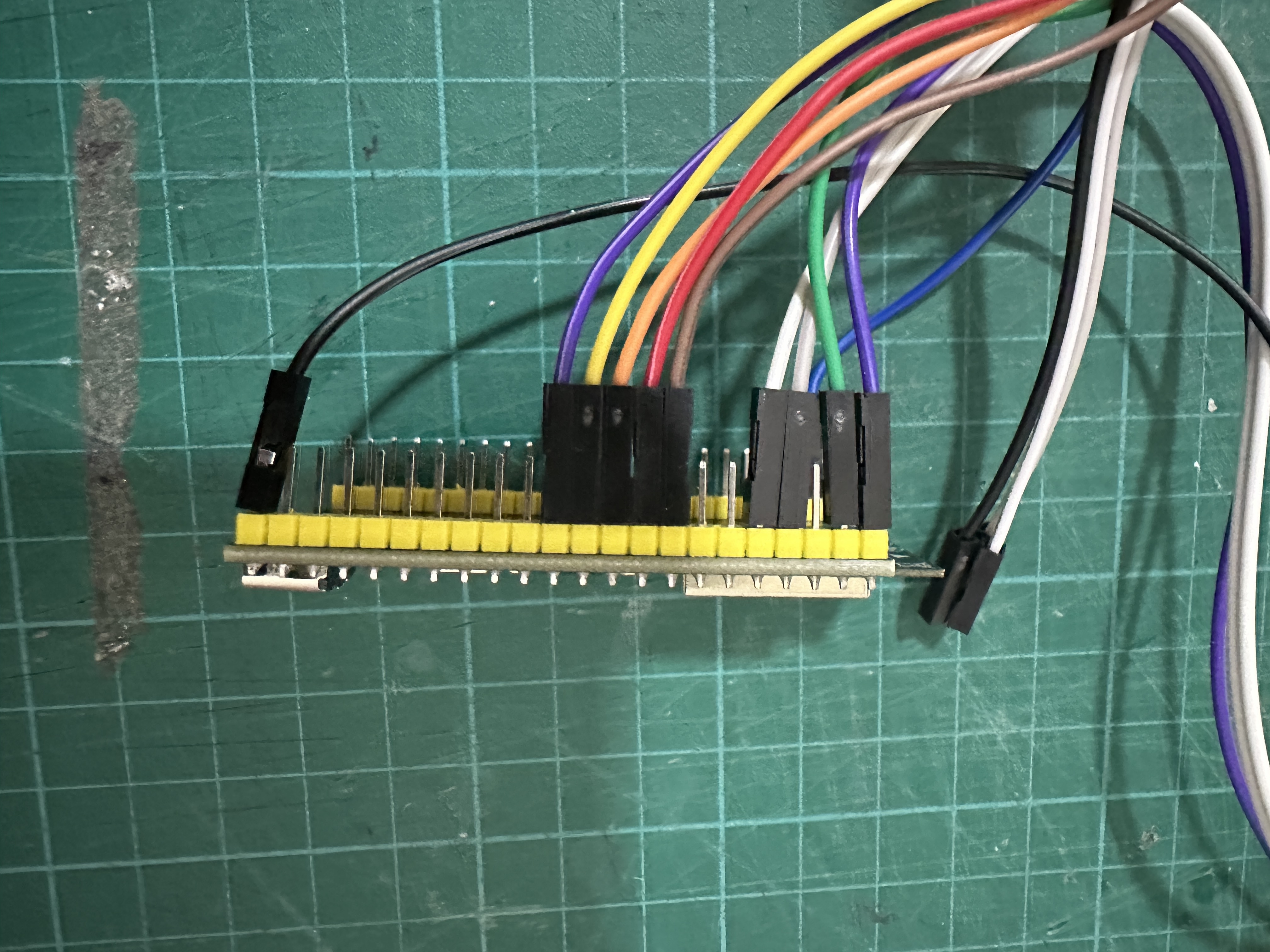
- Connect wires to PN532:
- Similar to the HX711, connect 7 Dupont wires to the PN532
- Install wires so they come out on the side opposite to the antenna (not the electronics side) (image below is a bad example and doesn't follow this recommendation)
- Configure the PN532 for SPI mode: with board poitioned so dip-switches on bottom right, set left switch down and right switch up
IMPORTANT: Many users miss the last step above about the dip-switches. Make sure you do it now !
-
Connect PN532 to ESP32-S3:
PN532 Pin ESP32-S3 Pin SCK 15 MISO 16 MOSI 17 SS 18 VCC 3V3 (next to HX711 connection) GND GND (next to HX711 connection) IRQ 8
- Install PN532 on Base:
- Place the PN532 into the rails on the right side of the base
- Position the antenna (white rectangle) facing outward
- Direct wires toward the rear of the case (they will turn back to reach the ESP32-S3)
- The narrow side of the PN532 should be parallel to the base
6. Test Before Final Assembly
At this point, test your configuration before closing the case. For this, refer to the Scale Setup Guide to ensure everything is functioning properly. This step is crucial as disassembly will require removing screws if troubleshooting is needed later.
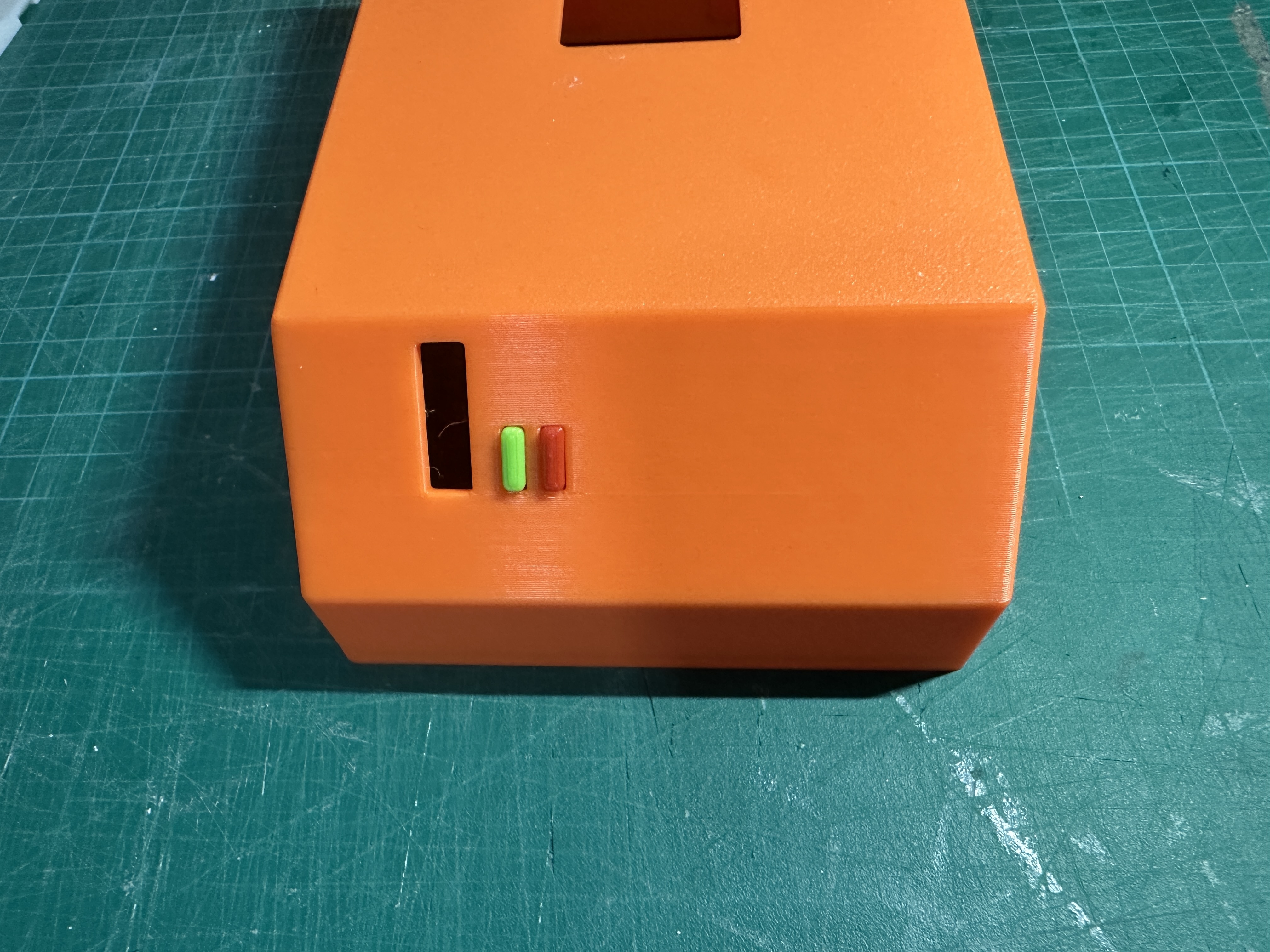
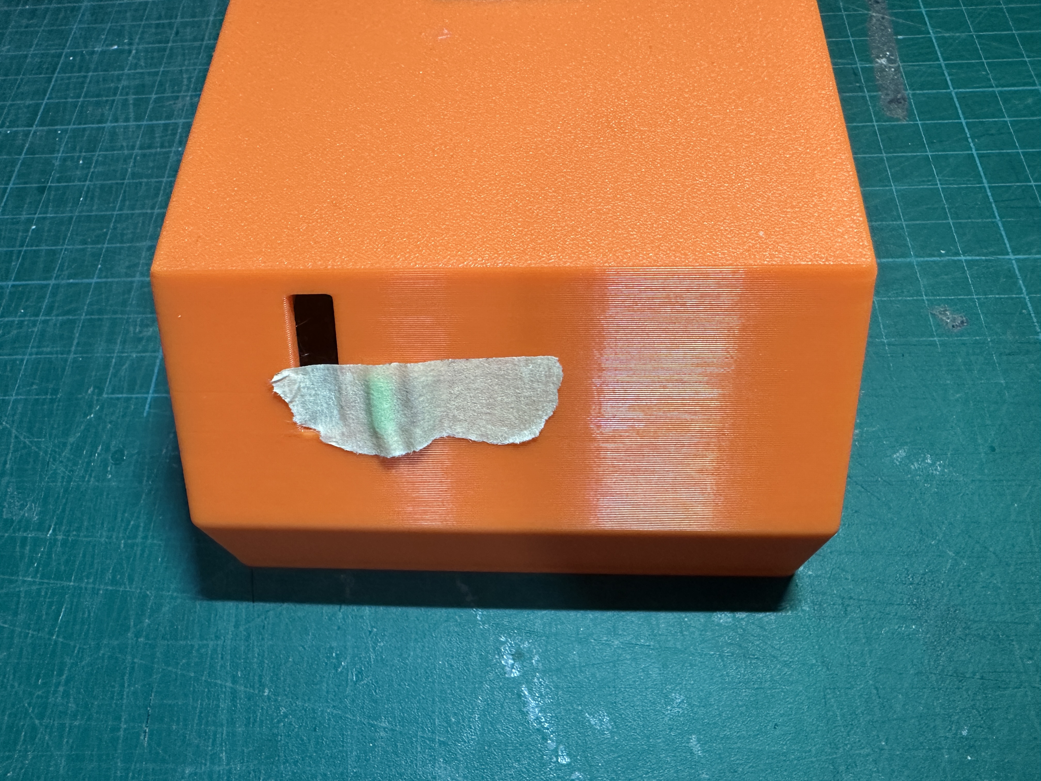
7. Final Assembly
- Prepare the Cover:
- Glue the beams to the right side of the case (especially helpful for visibility to the position of the PN532)
- Locate the two small buttons (originally colored red and green)
- Insert buttons from inside the cover pushing outward (red, for reset, to the right, green, for features use, to the left)
- Ensure buttons move freely (sand lightly if needed)
- Temporarily secure buttons with masking tape from the outside
-
Wire Management:
- Verify the ESP32-S3 is properly positioned
- Ensure all wires are clear of the load cell
- Keep wires below or to the sides of components, not extending beyond base edges
-
Attach Cover:
- Carefully place the cover over the base without pinching any wires
- Secure the cover using the two side notches that lock into the base
- Remove the masking tape from the buttons
- Test button functionality - you should feel them pressing the underlying board buttons
- The front vertical slot should reveal three LEDs at the bottom and a larger RGB LED at the top
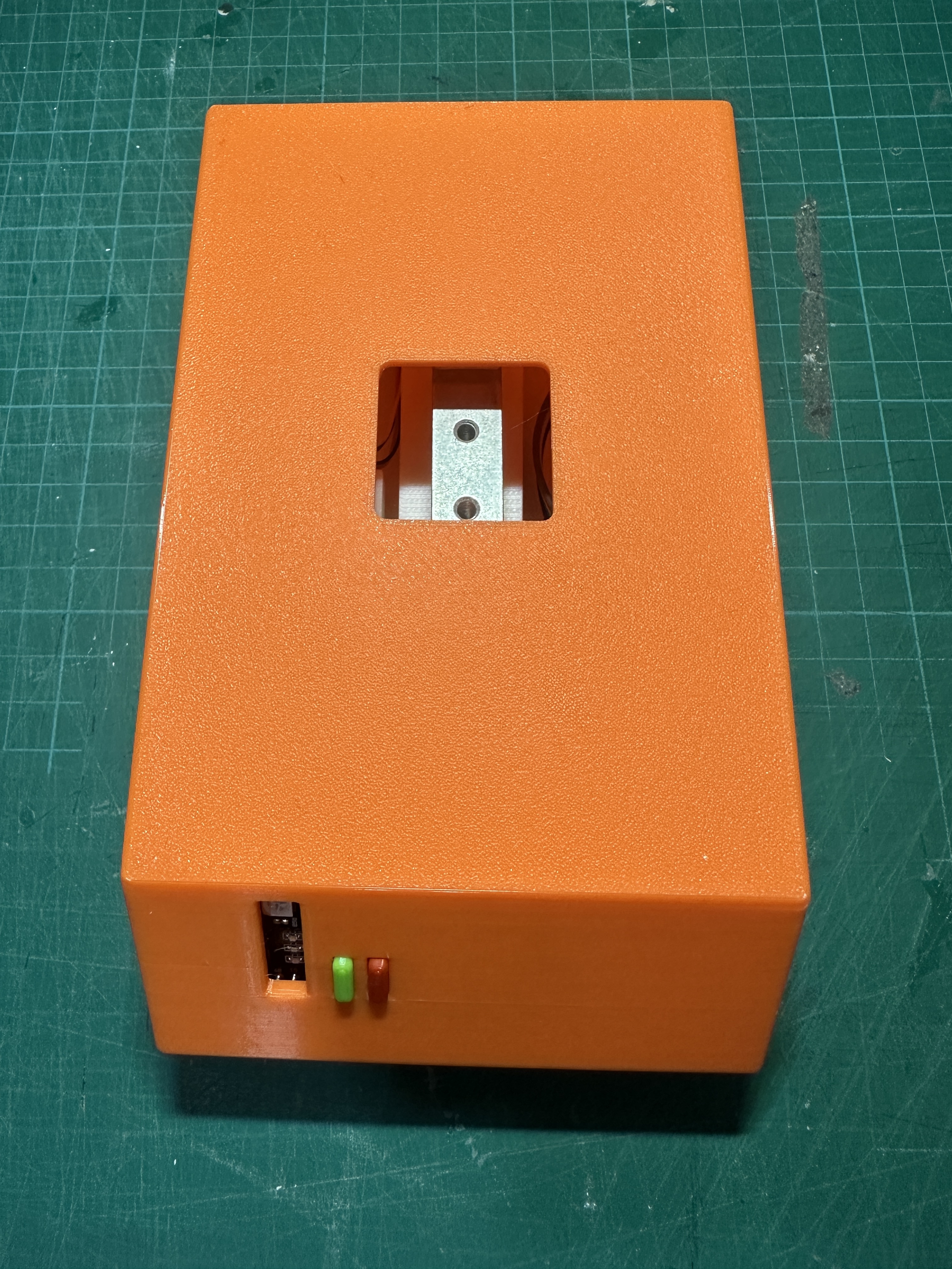
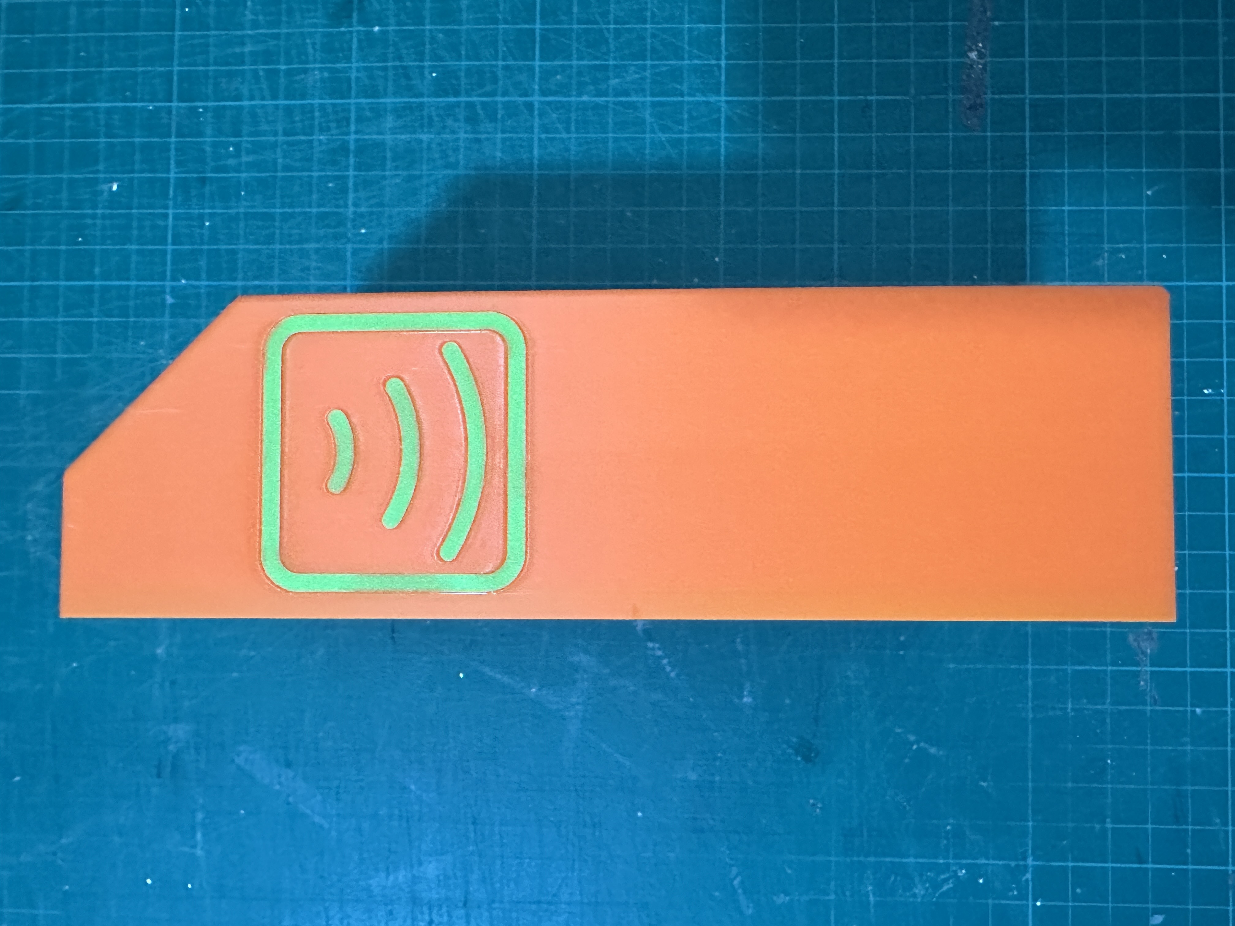
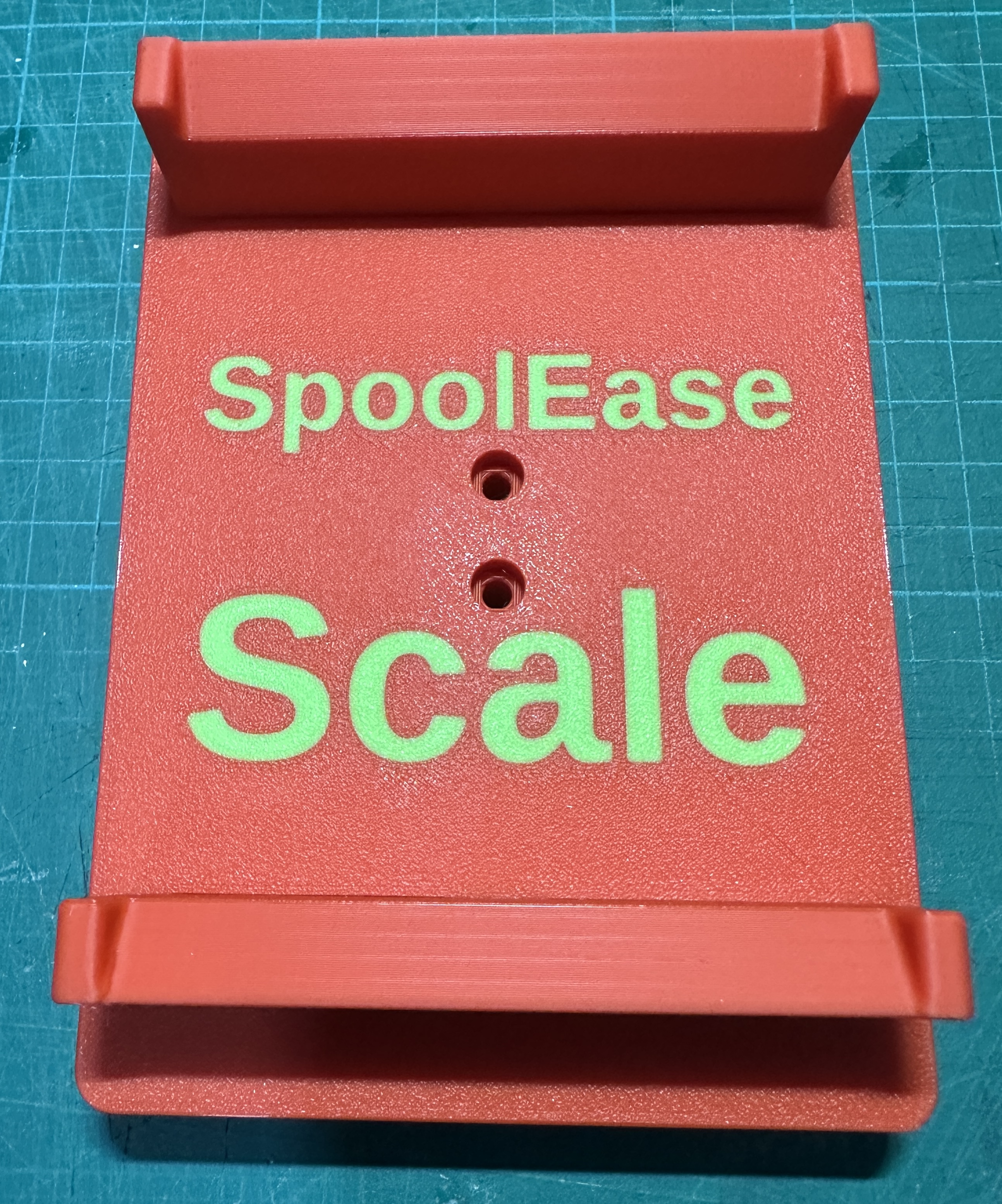
8. Install the Plate
- Insert the two Spool Supports into the plate:
- Position the sloped side of each support facing the center
- Ensure a tight fit in the plate holes, it may require some force to push them in (or add glue if hold not firm)
- Mount the plate:
- Place the plate with text facing to the front into the top square hole of the case
- Secure the plate to the LoadCell using the two M4x30 screws
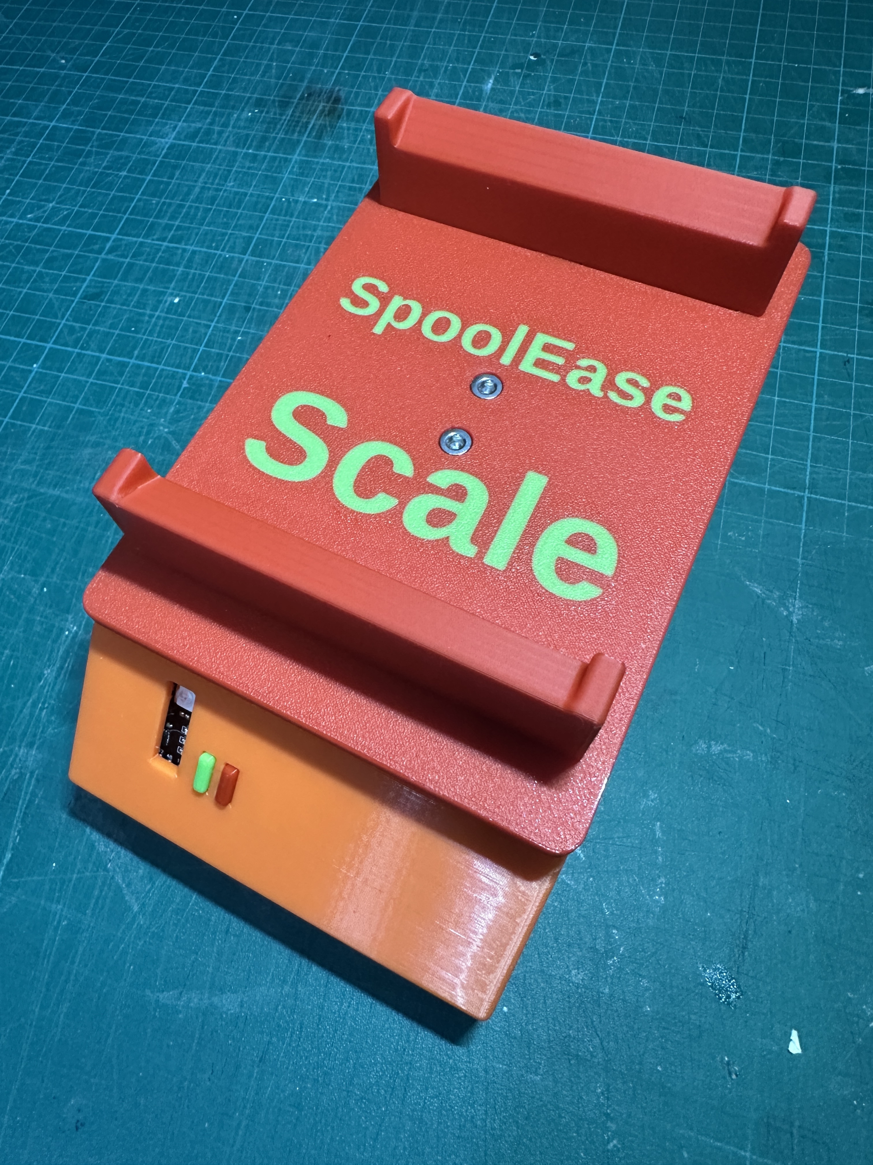
Congratulations!
You are the proud owner of SpoolEse Scale
Continue to complete the setup using the Scale Setup Guide